Extrusion format
This page contains information about the new Extrusion Format.
- dimensions
- part list
- power supply spec.
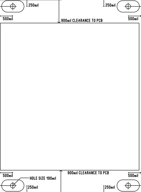
Dimensions.
Here is an example of EXTF-7.5, 5.5" wide module.
Here is an example of EXTF-7.5, 5.5" wide module.
| extf-7.5_dimensions-width5.5.pdf |
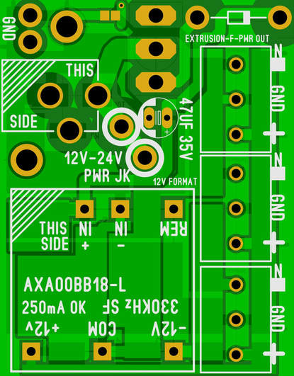
Here is an example of a power supply.
The power barrel is 1.462" down from the front panel top portion.
The power barrel is 1.462" down from the front panel top portion.
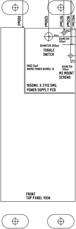
| extf-7.5_power_supply_example.pdf |
Part list.
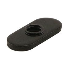
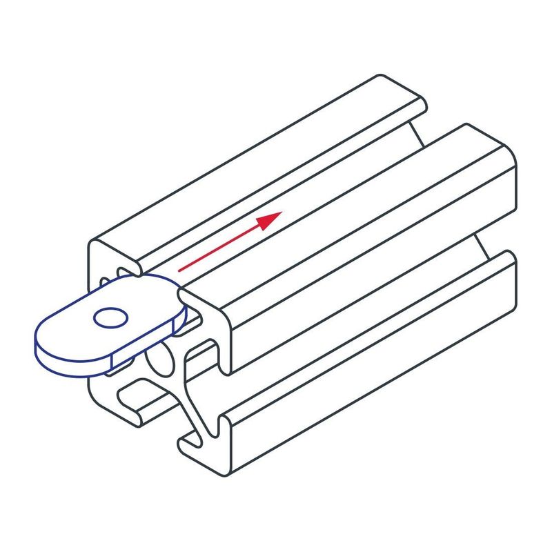
*80/20 Inc T-Slot 10 Series 10-32 Slide-In Economy T-Nut #3276
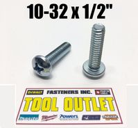
*FEET SCREW: 10-32 X 1/2" PHILLIPS PAN
RUBBER FEET + PCB + SLIDE NUT.
*MOUNTING SCREW: 10-32 X 3/8" PHILLIPS PAN
PCB + SLIDE NUT.
1X1 EXTRUSION (LEVEL 1 PCB)-DESKTOP
2X1 EXTRUSION (LEVEL 2 PCB SANDWICH)
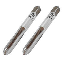
*M6 TAPPING TOOL REQUIRED FOR EXTRUSION PREPARATION.
*M6 SCREWS: M6X12mm FOR SHEET SIDES, M6X20mm FOR THICKER SIDES.
*80/20 Inc T-Slot 10 Series 10-32 Slide-In Economy T-Nut #3276
*FEET SCREW: 10-32 X 1/2" PHILLIPS PAN
RUBBER FEET + PCB + SLIDE NUT.
*MOUNTING SCREW: 10-32 X 3/8" PHILLIPS PAN
PCB + SLIDE NUT.
1X1 EXTRUSION (LEVEL 1 PCB)-DESKTOP
2X1 EXTRUSION (LEVEL 2 PCB SANDWICH)
*M6 TAPPING TOOL REQUIRED FOR EXTRUSION PREPARATION.
*M6 SCREWS: M6X12mm FOR SHEET SIDES, M6X20mm FOR THICKER SIDES.
|
|
|
|
|
|
M6 TAPPING TOOL
|
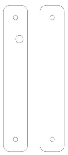
SIDE PANELS FOR 1X1 EXTRUSION. EXTF-7.5
Below is an example of a pair of side panels for EXTF-7.5. The pdf contains all the dimensions needed to drill your own holes.
One side gets a hole for the power barrel.
Below is an example of a pair of side panels for EXTF-7.5. The pdf contains all the dimensions needed to drill your own holes.
One side gets a hole for the power barrel.