|
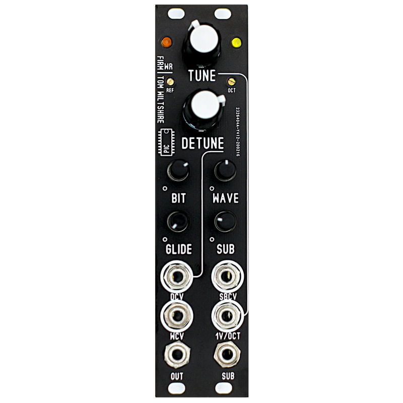
MODULE: TW DCO
DIGITAL OSCILLATOR, SOUND SOURCE WIDTH: 6HP CURRENT: TBA DEPTH: TBA PIC BASED DIGITAL WAVE TABLE OSCILLATOR BY TOM WILTSHIRE. PDF OF THE PIC CHIP CAN BE FOUND HERE. What does this do? This is a digital vco with on board wave table and sub oscillator outputs that are audible. You use this as a sound source. The Tune Knob Parameter is Quantized. As you turn the knob it locks to musical chromatic scale. Very musical module. CV Input sources: Wave table CV Sub Wave Selector CV Detune CV 1v / Octave Pitch input CV Outputs: Wave out, Sub out. -10 Octave note range from 8.18Hz to 8372Hz -16 Waves in the table -8 Sub Osc waves -Bit Crush Control, from 8-bit to 1-bit. 8 bit 62.5KHz Sample Rate. -On board Glide effect parameter. Price: $130.00 The zip file contains the PIC Datasheet.pdf and Wave forms Pictures. |
| waveform_pics.zip |
|
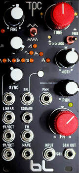
MODULE: TPC SLIM VCO
ANALOG OSCILLATOR, SOUND SOURCE, LFO WIDTH: 12HP CURRENT: TBA DEPTH: 1.5" Clearance, 1.3" min. ---------------------------------------------------------------- Two Stacker PCB manufacturing method. 1. Control PCB 2. CORE vco PCB ---------------------------------------------------------------- Discrete Triangle Core VCO What does this do? This is an analog vco based on the Bergfotron Advanced VCO. It has heavy modification compared to other buchla vco's. It will track much better then the competition. Why? because this is using a VCA based tracking system instead of the matched transistor system. The 'Lock' switch allows for setting up your favorite reference Frequency. For example you can set it up on Zero Volts equals low Note 'C'. You use this as a sound source. You use this as a precision LFO. You get a bonus analog sample and hold. There are two possible sound source outputs: -Wave Out. This has 8 possible wave shapes: Triangle, Saw, Double Saw, Pulse Width, Sine, Ramp, Even Harmonics, and Double Pusle wave. All of this is selected by push button. The selector circuit is using a Precision DG412 IC chip, so there is absolutely no bleeding. There is of coarse CV input for the selector (by Triggering). All 8 waves are roughly -5/+5 (more than). I like my signals hot, so it is a bit more then your wimpy vco's. My clients know the way I roll already. -(Positive) Static Square Wave Out. This is a great clock source, it is also a great sync source for other products. The analog sample and hold is using the internal VCO as the 'clock'. You simply patch a sound source on the 'input' and use the output to monitor the result. The (red knob) Tune knob above is used to control the S&H rate. This product is the evolution of the 'Transistor Pyramid Core' saga. This product has all the research and development I spent working with Analog vco's. Price: $289.00 |
|
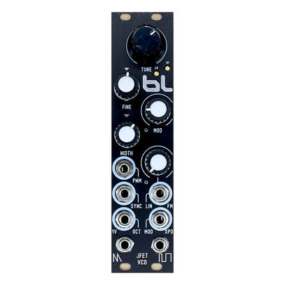
MODEL: BLM JPJFET VCO
Analog Saw Core VCO Width: 6hp Depth: 1 Stack PCB. Skiff Compatible. Current: -32mA, +35mA Circuit type: Analog What does this do? This is an analog Voltage Control Oscillator that is Saw core based. It uses a JFET part inside to generate the Saw wave. This is very similar to a famous Roland Vintage product, but this is using modern equivalent parts. The 1V per Octave circuit is also not transistor based. It is using a modern VCA circuit for 1v/octave tracking. The 1V/octave circuit is also using the recent Op Amp OPA1678. OPA1678 has 110db Noise Floor, and 0.0001% THD. The power rail capacitors are Tantulum type, and the timing Capacitor is a 2% 4.7nF through hole film type. 0.1% Reference voltages were used for the tune and fine tune. Wave Outputs: Saw wave, Pulse Wave. Both are operating from 0v. -5v/+5v (AC signal) Pulse Wave has a Pulse Width Modulation input. Saw Wave is static, and the PWM does not do anything to it. Modulation Inputs: Linear, and Exponential. 1. Modulation with Attenuator. Exponential Type. 2. Linear with Attenuator. 3. 1V/Octave Direct Input. Hard Sync Input. This requires a Positive Square Wave. Softer AC wave forms will do a very soft sync effect. Buy One Now |
| blm-jpjfet-vco_saw_core-mk2.pdf |
|
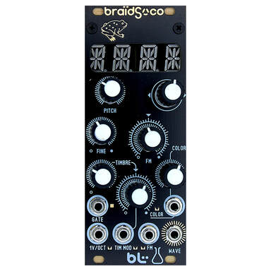
Model: Macro VCO
Width: 10hp Current: +88mA, -6mA Black Color Yellow Color What does this do? This product is a Macro VCO that uses Braids Firmware written by Emilie Gillet. There are many different models on this like Drums, and Bells. CC-BY-SA-3.0 Project. Files for this can be found on my Survival Page. |
| braids-sam_ren_v0.4.zip |
The above zip file contains a .hex file for the alternative firmware for Macro VCO called: braids renaissance. This hex file is for people who are building there own Macro Vco's or braids.
|
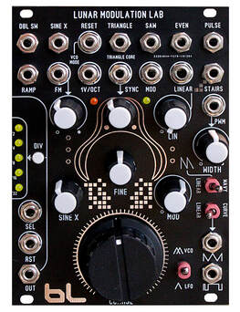
Model: BLM Lunar Modulation Lab VCO
Analog Oscillator, LFO,VCO Width: 18hp Current: +91mA,-61mA This is my Flag Ship Analog VCO What does this do? This product produces continuous wave forms that can be used as an LFO or audio rate VCO. There are 11 possible wave form outputs. This is a discrete, triangle core design based on the Bergfotron 'Advanced' VCO. This particular version uses a VCA based exponential converter for the core 1v per octave converter. Features: -11 Wave Form Outputs: Ramp, Double Saw x2 Frequency, Sine with Level Out, Triangle, Saw, Even Harmonic, Pulse with PWM, Falling Stairs, Folded Triangloid, Pulse Train, Sub Generated Pulse Output (Divider) -VCO and LFO mode. -Triangle Core Design -Linear FM -Exponential FM, with Bi-polar Knob -1v Octave direct input -Sync input -Reset circuit (VCO mode only) -Trigger input for selector (Divider circuit) -Reset circuit for divider circuit Price: $325.00 |
| blm-lunar_modulation_lab_vco_2020.pdf |
|
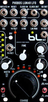
Module: Phobos Lunar LFO V2.0
Width: 12hp Current: +80mA,-50mA Analog PLL based LFO/VCO This module contains about 5 modules in one. You get a lot of features. This is using a Phase Lock Loop based internal patch to create the oscillation (LFO). I then give you access to the clock divider used in the Phase Lock process. Think of this module as a 'phase lock loop for dummies'. Just play and forget kind of module. No menu diving or complicated stuff to remember. This LFO can go audio rate or really slow using the toggle switch to decide LFO/VCO mode. There is an internal CV switch for you to select from 6 wave forms. The special wave form is the step generated wave. It sounds like a quantized ramp wave, and moves at half the overall internal lfo rate. There is a nice Level out knob to control the LFO wave output. This LFO has very HARD sync, that will reset the lfo. The other half of this module contains a clock divider that also uses a CV selectable output. The clock divider can also go audio rate and sound like a sub harmonic generator when in audio rate. At very high frequencies (COARSE knob fully clockwise), the clock divider will lock up, this is due to the cmos chip, this is normal. The clock divider can be used with internal clock or external clock. This is a fun performance type of lfo with just about all the features an LFO should have. There is 1v/ octave tracking of about 4 octaves when used as an oscillator. This product is for most part more of an LFO. The best patch one can do with this product is a 'cross' patch from the Phobos Lunar LFO, and have it patched to your Oscillator module. Then patch your oscillator to the CV waveform select on the Phobos. Hear what your oscillator sounds like, it will blow your sound pallet. I demonstrated this patch at the Knob Con 2016 conference. Price $199.00 |
|
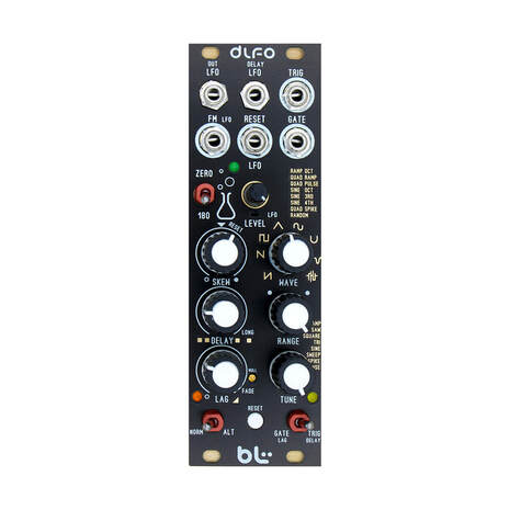
Model: Mini Digital LFO Width: 8hp Current: +28mA, -27mA LFO, Delayed Time/Lag Processor Audio Rate FX? Yes, you can hear the LFO. What does this do? There are two parts to this module. -LFO side -'Tremolo' type LFO processed through a Delayed Time/Lag circuit LFO side -16 possible wave shapes. Two banks: Normal and Alternative, selected by toggle switch -Range Knob -Frequency Tune Knob -Reset-able Manual Push Button -Input Jack for External Reset -Zero Degree, 180 Degree Flip Switch for LFO Output -Level Out Knob for LFO -FM input for LFO Modulation 'Tremolo' Delayed Time/Lag Side -Gate and Trig inputs -Manual Trig by toggle switch -Delay Knob -Lag Knob Price $99 |

| blm_mini_digital_lfo.pdf |
|
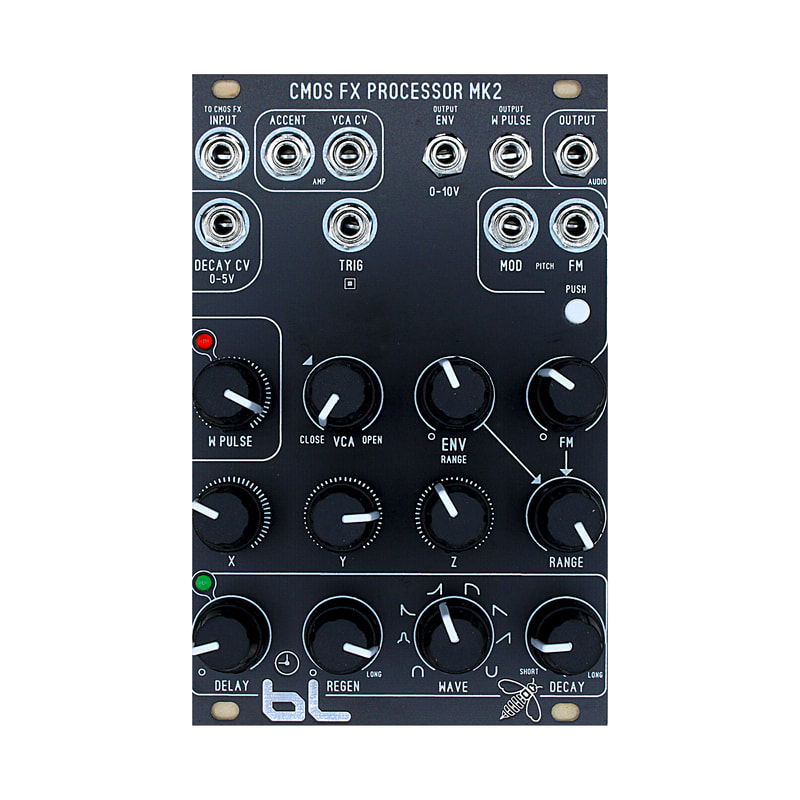
Model: BLM CMOS Fx Processor MK2
Width: 16hp Current: +35mA,-34mA PCB Stack: 1 level. Skiff compatible. What does this do? This module has all the internal circuits to complete a voice: sound generation + envelope generation + amplifier control. The sound generation is interesting. The core is using 3 CMOS based oscillators that are performing exclusive 'or' logic. This is known as 'XOR' ring modulation. This entire circuit is being voltage starved, a technique common among the advanced circuit bending hobby. For example, portable vintage toys that use batteries sound different as there batteries loose voltage. I designed a CV controllable circuit that simulates the 'dying batteries' scenario. This is where the product's name comes from: CMOS FX Processor. Incoming audio is internally conditioned to be those dying batteries. To my knowledge I don't think there is any other euro format product that uses this technique. -CMOS FX INPUT jack has a capacitor on it's signal path, making this an AC input. -MOD INPUT jack is a DC signal path. -FM INPUT jack is also a DC signal path, but with level control (attenuator). Envelope Generator This is a digital based 1 shot circuit, that has 8 wave forms. The decay knob controls the tail of the envelope. There is no parameter for attack. Some of the wave forms have set attack times if you require some 'fading' in on the control. -Regeneration 'REGEN' parameter is a feedback. This controls the looping of your envelope. -Delay parameter controls the time until the next 1 shot of your loop. -Decay knob needs to be adjusted as you experiment using Regen and Delay parameters. Shorter decay times work best and make the looping faster. -Envelope Output is 0-10V. Amplifier Control The internal circuit is an OTA based '13700' vca design. -Accent input jack is a POSITIVE only conditioner. For example if you patch a -5/+5v signal, only the +5v portion reaches the VCA control. This is good for making the audio louder at given intervals, but not making the audio 'mute'. -VCA CV input jack is a direct DC coupled input. This will make the audio fade in and out of volume. Both positive and negative values make it to the VCA control. How to use this module. For best results you will need a sequencer or sample and hold from a digital fancy module. You can practice first by patching this to the 'FM' input and find your sweet spot with its level. You will need to patch a 'tempo' to the trigger or you can use the W Pulse clock to trigger this product. Once you got the hang of the module, make a sequenced based patch with your other modules. Use the CMOS FX Processor at the end of the audio signal path chain to 'Process' your audio. Your going to here some bizzare techno. If you have a scope, the waveforms on the output are really crazy to see. Price $168.00 |
| blm_cmos_fx_processor_mk2.pdf |
|
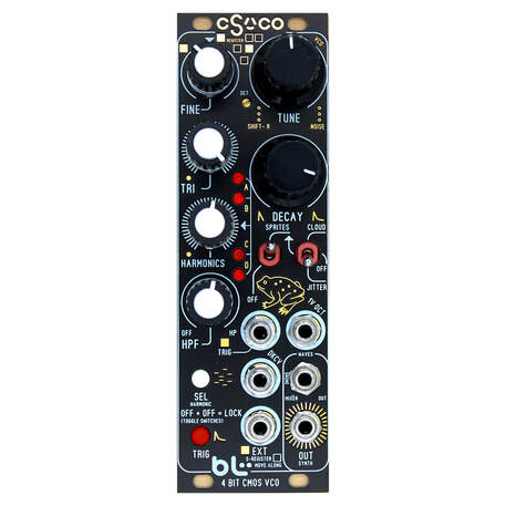
BLM CSR-VCO
Width: 8hp Current: +150mA, -140mA What does this module do? This is a complete mini synthesizer that only requires CV and Gate from your midi to cv converter. You can use an AKAI Mini Keyboard or Arturia KeyStep for example. As long as the product has CV and GATE outputs, you can musically control the CSR-VCO module. This is a great first-time module, or a great percussive voice to add to your electronic singer section. The CSR-VCO is similar to the ‘toy’ algorithm on the mutable braids module, and the wiard noise ring (kinda). -When the Shift Register is put into random mode using the toggle switches you can create the classic arcade noise sound found on the atari, and defender arcade game. -The shift register can loop into more musical overtones, using the toggle switches, that also resemble early atari pulse wave sounds. These are the only two modules I was able to confirm that use the same related approach of using many pulse harmonics to sculpt the sound. There is no firmware, or simulation happening on the CSR-VCO. The module is an analog and cmos logic hybrid module. There are many modular sections involved to make this happen. It would take many modules to attempt to make your own CSR-VCO patch on your modular. You would need the following: Triangle VCO, x2 clock generator, Shift Register module, High Pass Filter, VCA, Envelope Generator, Sub Division Pulse Generator Module, Logic xor, Logic AND, Logic Invert modules, and a mixer module. This would easily take up 64-84hp. Such a complicated patch on your system would probably not work as good as the CSR-VCO. The CSR-VCO is a Bright in Sound. This module is not good for bass. It resembles cheap toy electronics from the 1980’s. The CSR-VCO excels at higher frequency ‘piano’ like sounds. It can also be used for bright percussive sounds. All of this tracks +5 octaves, musically. The CSR-VCO contains so many over tones (mathematically sub divided), that it is indeed producing chords. The EXT trigger input ‘rolls the wheel of chance’, and changes the over all tone of the shift register. The CSR-VCO seems to sound more ‘Minor’ at times, it gives a more creepy, spooky set of chords. I can’t confirm this, but that is the impression I get from changing up the shift register. Price $168.00 |
| blm_csvco_-manual.pdf |